In this instructable, I’ll demonstrate to you how to build an electric heating machine and seven different uses for it. Induction heating has significant applications, and it is extremely simple to construct. I’ll go through the implementations first, and well you can decide whether you want to build either of these outstandingly useful computers.
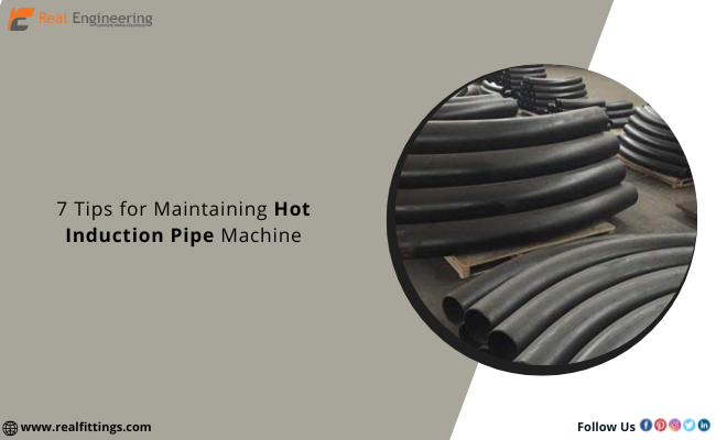
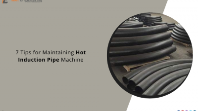
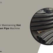
The hot induction pipe bending machine is bent by passing this through an inference machine. An initiation coil is used in this device to heat a thin strip of the piping system. A Hot induction pipe bending machine with both the preferred inclination angle is generated as the pipe is tried to push through to the machine.
The heated substance just outside the ignition coil is quenched by spraying water upon that pipe’s external surface. The un-insulated pipe along either side limits the temperature increases of the closely heated piece of pipe, casing diameter suggests that financial on such cooling.
Mark Up the Following Guidelines
• If the thickness of the pipe wall varies from around the perimeter, the thicker segment must establish the extrados bend.
• Once the flexing operation has begun, no stops should be allowed.
• Maximum temperature swings at two places (180 degrees apart), having to bend pace, and flow quantity or stress of coolant fluid should be noted and long history.
• Digital temperature accuracy ought to be + 10 oF (+ 5.5 oC); speed measurements ought to be + 0.02 in. (+ 0.5 mm) per moment; and stream precision should be + 2 percent of flow stipulated in the Company’s Flexing Process.
• If any of the ASME 16.49 / ISO 15590-1 vital Variable differ from all those specified in the competent Company’s Bending Process by much more than the tolerance specified in ASME 16.49 / ISO 15590-1, the pipe should be thrown away.
• Except as otherwise specified by the manufacturer, the maximum bending speed should be between 25 and 50 mm/min. Furthermore, the cooling process should happen instantly after the initiation, resulting in a short Austenitizing cycle as well as a slaked structural urban.
• Post-Bend High Temperature – To attain the required greater standard, bends ought to be heat resistant after having to bend.
Before beginning induction bending, the automaker should meet the criteria of the Manufacturer’s Bending Operation for Induction Bending by establishing and testing a Qualifying Bend in conformance with the Society of testing and materials 16.49 / ISO 15590-1. The process qualifier illustrates that the Company’s Bending Procedure can generate bends with appropriate aspects and mechanical characteristics.
• The Requirement Bends should indeed be made with the same content heat as manufacturing deforms and according to the suggested Company’s Bending Process.
• Post Bend Heat Treatment will be included as part of a course’s tests, along with a specific description.
Manufacturing Bending Procedure
• Bending/heating hardware characterization
• Temperature of initiation bending
• Temperature dependence expected all over plate thickness
• NDE operation for cooling
• Directional regulation tools and procedures
Essential Items
The criteria are met and their allowable variations assist in determining when you need to re-qualify. The following are critical variables with a Hot induction pipe bending machine
• Measurements
• Creating (speed, temperature)
• Refrigerant
• The frequency of heating up
• Heat Treatment Following Having to bend
• ISO 15590-1 Table 1 sets the maximum allowable variants.
Dimensions
During the bending process, the behavioral analysis and requirements should be followed:
• Before trying to bend, the outer diameter of the piping system should be evaluated ultrasonic-assisted at approximately 300 is along both inlet and outlet radii of the curve.
• Within a week of bending, the inner surface of the pipe should be evaluated ultrasonic-assisted at the same places as before having to bend. Furthermore, the inner surface of the digressions should indeed be mechanical means measured. These measurements are needed four times around the diameter of the pipe, at these welding edges of the bend.
• Ovality really shouldn’t surpass 3% of the diameter size throughout the body of the bend and 1% again for digression portions, as evaluated by the distinction among lower limit radii as well as determined by calculating per ASME 16.49 / ISO 15590-1.
• The diameter should be measured at the start or stop of the bend locations and at all points throughout the bent portion to ensure compliance with the required tolerances.
• For subsea flexible riser: The internal diameter at any location of the bend should not be less than 95.7% of the nominal internal diameter of the pipe, and not less than 98.6% of the nominal internal diameter of the flexible riser.
• All other post-bend dimensions should be within the tolerances of ASME B16.49, Section 12 and ISO 15590-1.
Testing With the Induction Bend
The minimum inner surface at the middle point of the outer periphery of each manufacturing bend should be calculated and recorded to ensure it is equal to or better than the minimum threshold sheet thickness stipulated in the bend configuration.
Ultrasonic Testing (UT) must be performed on the whole pipe perimeter 100 mm home from the beveled ends of each non sequitur length to ensure that no ply form deficiencies are prevalent. Regions that cause more than 50% of the back wall acoustic wave or an ability to reflect slightly greater than 50% of reflective thinking should be rejected.
Also Read:
What You Need to Know About Buttweld Pipe Fittings?

